
MG-Rover Pektron SCU - Technical Information
The Pektron SCU was introduced by MG-Rover in 2003 and was designed to replace several electronic modules and integrate all of their functions into one module.
It also employed a more secure communication method for the remote fobs, this along with other design features gave a higher Thatcham security rating.
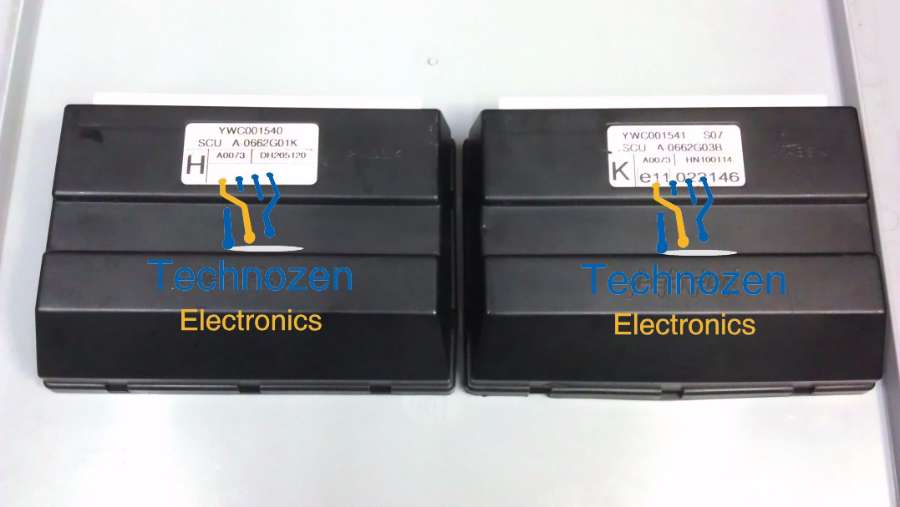
It has the following part numbers;
YWC001540
YWC001541
YWC001551
Previously the various modules used were;
5AS module: Alarm, Immobiliser and Central Locking functions.
MFU (Multi Function Unit): Provided timing and switching functions for various circuits.
Drivers Window ECU: Controlled the drivers window operation and gave one touch down and time delay opertion.
Flasher Relay: Timing and switching for the indicators and hazards, double speed flashing for bulb failure warning.
The SCU was introduced in production from the following VIN numbers;
Rover 25 /MG ZR / Streetwise - From VIN RF 732814.
Rover 45 / MG ZS - From VIN RT 637209.
MG TF - From VIN RD 620459
MG TF LE500 - All production vehicles.
MG TF 85th Anniversary - All production vehicles.
The SCU has the following configurable options;
Can be programmed with up to 10 remote fobs.
Programmable EMS (Immobiliser) and EKA codes.
Vehicle Configuration: production and customer options;
Basic Central Locking enable.
Superlocking Yes/No.
Superlocking activated by Single or Double fob press.
Speed activated locking.
BBUS sounder or horn sounder for alarm.
Electric window enable.
"One shot down" drivers window.
"Auto before Inch" - drivers window moves down in one
inch increments.
Window delay - windows work for a period of time after
ignition off.
Auto door
relocking.
Front fog lamps.
Tailgate release.
Rear wiper/wash enable.
Front Dribble Wipe - a delayed single wiper sweep after screen wash operation.
Programmed Wash/Wipe - wipers are automatically activated on screen wash operation.
Headlamp washer.
Intermittent wipe duration, 1,2,3 or 4 wipes.
Ultrasonic sensor enable.
Dash switch type - latching or soft touch (facelift) type
switches.
Inertia switch input - petrol or diesel.
Mislock sound.
Perimetric alarm exclusion.
Interior lights activated on disarm.
Hazards active on inertia switch trigger.
Transit mode sounder.
Factory mode.
The information below is taken from my SCU technical thread on
the mg-rover.org forum...
http://forums.mg-rover.org/showthread.php?t=384938
The SCU suffers from problems that can be categorised roughly as follows...
WATER INGRESS (25, ZR and Streetwise only).
Water enters where the wiring loom passes through the bulkhead into the engine bay, in many instances the rubber sealing grommet wasn't seated properly in production.
Water runs along the wiring loom and enters the SCU. If the SCU had been mounted with the connector strip facing downwards the problem of damage would not have existed.
In cases of water ingress there will be corrosion visible on the connector pins of the SCU connector block.
The first item to fail will be the radio receiver circuit board, this is mounted at right angles to the main board and water will lodge on it.
Fault symptoms will include poor fob range or no fob operation whatsoever.
If caught early the damage caused by water ingress should be minimal and drying the board thoroughly will restore full operation.
If the SCU is damaged beyond repair then it is possible to copy the data from it and program a used board with this information, this process creates an identical clone of the original and retains the configuration and original fobs.
With a bit of dexterity the SCU can be rotated in its mounting so that the connectors face downwards and I would suggest that all owners of a 25, ZR or Streetwise carry out this simple fix.
FOB FAULTS.
A design peculiarity of the SCU is that it will not allow diagnostic communications while it is the armed state. This means that new fobs cannot be coded "ON VEHICLE" if the originals have been lost or don't work.
The MG-Rover solution was to fit a new SCU and program new fobs.
Now a specialised diagnostic rig exists to allow the SCU to be unlocked and new fobs to be programmed.
A very common problem with the original fobs is corruption of the rolling code data because the fob has been exposed to the immobiliser systems of other vehicles. This problem was the subject of an MG-Rover technical bulletin, TT0122, in 2004.
It identified the following vehicles/manufacturers;
Any BMW vehicle.
BMW Mini.
Rover 75 / MG ZT (use a BMW based system).
These vehicles use a two-way transponder based system and the data transmissions can corrupt the Pektron fobs.
Never keep these fobs on the same keyring with the above.
If a fob is corrupted in this way there is no reset or repair and the only solution is to program a new fob.
As there is no resynchronisation option to match the fob's current rolling code position to that expected by the SCU, the fob buttons should NEVER be pressed while the fob is out-of-range of the vehicle.
If the fob and SCU go out of synchronisation then the only solution is to program a new fob!
The OE two button fobs which were used on the MG TF and pre-facelift vehicles with no electric boot release are no longer manufactured. In all instances a 3 button fob can be programmed to these vehicles.
The only OE 3 button fob that is currently manufactured is the MG baged version, part number YWX000360.
Be aware that the OE fobs were manufactured with two different transmitting frequencies, 433MHz and 315MHz, the latter was used for Japan and Australia.
A 315MHz fob will not operate a 433MHz SCU and vice versa.
An aftermarket 3 button fob is available and has proven to be very reliable and it is significantly cheaper than the OE type. The only slight downside of this fob is that it doesn't support the "friendly mobilisation" feature where the immobiliser is disabled automatically when the ignition is turned on, it will require the unlock button to be pressed to cancel the immobiliser.
PLEASE TAKE NOTE OF THE FOLLOWING!
When buying replacement fobs please make sure that they are supplied with the 22 character code, this information is used to program the fob to the SCU.
Used or secondhand fobs cannot be re-programmed.
Fobs can be transferred from one SCU to another providing the relevant fob data (a 28 character hexadecimal code) can be extracted from the source SCU and re-programmed to the destination SCU.
SCU MEMORY CORRUPTION.
I have seen many units which have suffered loss or corruption of the configuration data stored in the SCU memory chip, depending on the severity of the problem you will be faced with one or more of the following scenarios;
Fobs are found to be transmitting but do not operate the central locking or disable the immobiliser.
The engine starts but only runs for a few seconds.
Some of the SCU controlled circuits no longer work, ie. central locking or drivers window.
The SCU memory loss/corruption usually happens after the battery was allowed to go flat, the car was jump started or the SCU was disconnected/reconnected while power was present.
The memory file can be rebuilt but if the fob data portion has been lost then new fobs will need to be programmed.
CIRCUIT FAILURES.
Common problems with this module include;
The horn does not operate.
The drivers window only moves in one direction or does not operate at all.
The rear foglight does not operate.
The central locking only locks or unlocks or does not operate at all.
The doors are deadlocked.
The windscreen washer / rear window washer does not work.
The intermittent wiper function does not work.
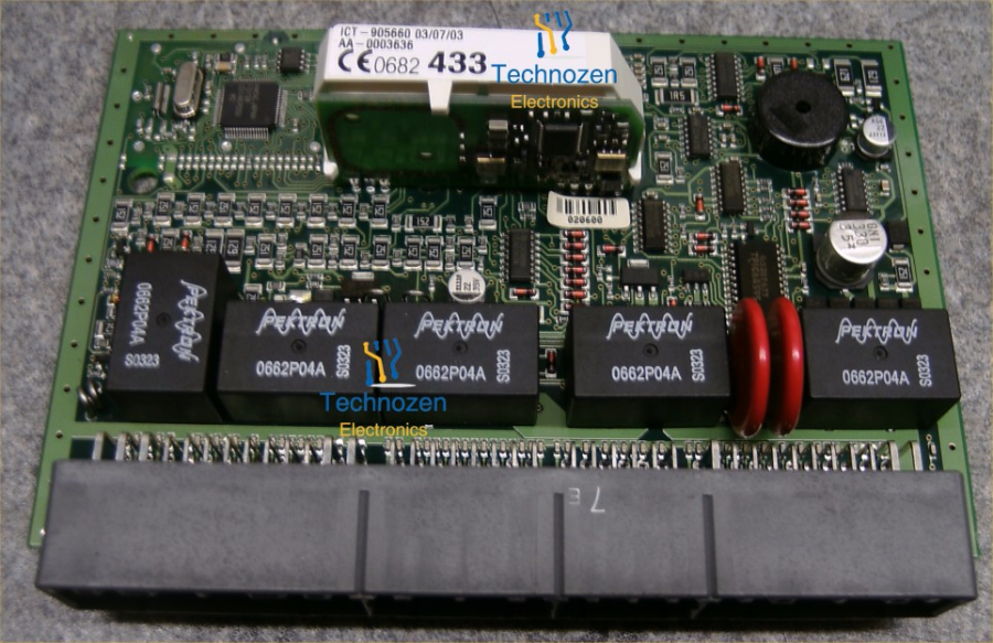
These problems are caused by failure of the Pektron branded control relays, the SCU contains five of the same type 0662P04A relay.
The relays are of poor quality and always fail with an open circuit relay coil caused by corrosion of the fine wire used to wind the coil.
Each physical relay contains two separate electrical relays, as shown in the picture below...

Below is a picture of the SCU circuit board showing the five relays and their individual function.

A less common problem is a circuit that stays switched on all of the time, ie. horn sounds constantly or the right or left side indicators stay illuminated.
These type of faults are usually caused by failure of the TPIC6A595 or TPIC6C595 driver IC's which are used to switch the relays on and off or drive external circuits.
SCU REMOVAL
On all vehicles the SCU module was relocated or secured to withstand the Thatcham "5 Minute" attack criteria, however it is relatively easy to access on some vehicles but a complete pain on others.
The biggest challenge is when the SCU has to be removed from a 25/ZR/Streetwise that has aircon fitted.
On these vehicles the SCU is fitted between the bulkhead and the aircon evaporator housing. Access is gained by removing the glovebox but the evaporator housing cannot be removed as it is connected via pipework into the engine bay.
The original removal instructions were based on the fact that the early SCU bracket had a "hook" at its top which simply hung on a stud welded to the bulkhead. All that was needed was for the lower evaporator housing nut to be removed, the housing could then be pulled away from the bulkhead and the SCU lifted off the stud.
All change....
The mounting bracket was modified and it now has a single hole instead of the "hook", it still fits onto the stud but a plastic cap keeps it in place. The evaporator housing has to be removed to allow the SCU to come free from the mounting stud.
The official removal process requires that the aircon system is degassed and the evaporator disconnected.
Below is a picture of the revised bracket design.....

Some people have managed to loosen the various clips and brackets securing the aircon paipework in the engine bay, this allows more movement of the evaporator housing
and slightly better access to the SCU, but it is still a difficult and time consuming procedure.
If the car does not have aircon fitted then it is easier as the evaporator housing is just an empty plastic box and is easily removed.
The procedure is as follows;
Remove the glovebox, two 7 or 8mm bolts secure the hinges to the dashboard framework.
Remove the metal strengthening strap that runs horizontally, one bolt on either side.
The evaporator housing is on the right hand side.
Remove the two large cross-headed washered screws and the two 11mm nuts.
The complete housing will now pull forward.
Below is a picture of the SCU with the later type mounting bracket in its position on the bulkhead, the hole on the left is where the aircon pipework
enters.

On the 45/ZS the SCU is fitted in the centre console framework, the complete console has to be removed.
The SCU is located behing the heater control/cigarette lighter sections.
On the MGTF the SCU is also fitted in the centre console, roughly in line with the bottom row of
switches.
Access is gained by removing the console side panel in the passenger footwell, the panel is fixed with a few screws and the footwell light wiring has to be disconnected.
The SCU retaining bracket only has to be removed on the passenger side but the screw head is partially obscured by the bracket being bent over by 90 degrees.
The M5 screw used has a 5 lobe design, a security variation of the standard TORX design known as TORX-Plus.
The size is designated as TS25.
The picture below shows the screw and the correct bit..

The correct bit can be difficult to source but I now keep them in stock.
In true MG-Rover style I have found standard Pozidriv screws and 8mm bolts used on the SCU bracket.
RELAY TESTING AND REMOVAL
Despite being a multi-layered circuit board with through plated holes, the relays are easily removed with a standard soldering iron and either a de-solder pump or de-solder braid.
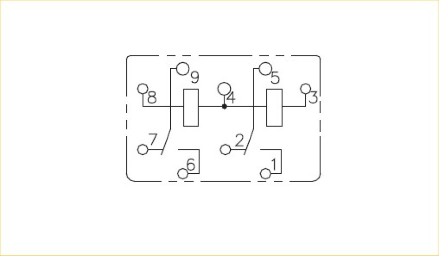
The relay coil(s) going open circuit is the usual cause of failure, each relay coil has two connection pins and a simple test is to measure the coil resistance with a multimeter. A working relay coil will have a resistance of 170 - 220 ohms. I have yet to see relay failure caused by contacts welding together, despite their small size they are able to handle the large currents, especially the central locking and drivers window relays.
Below is a connection diagram of the relay, a pin of each coil shares a common connection (Pin 4).
The coil resistance should be measured across Pin 8 and Pin 4 for one relay and Pin 3 and Pin 4 for the other.
My SCU technical thread on the mg-rover.org forum...
http://forums.mg-rover.org/showthread.php?t=384938